Solar inverters inevitably experience malfunctions over time during daily operation. When a malfunction occurs, fault code alarms will appear. The instruction manual provides a corresponding meaning and explanation for each fault code, helping users quickly identify the root cause of the problem and effectively mitigate its impact. A thorough understanding of the inverter's fault codes not only helps ensure the safe and stable operation of the equipment but also significantly improves maintenance efficiency.
Taking the Xindun parallel hybrid inverter as example, Xindun will now explain in detail the meanings of various fault codes and basic troubleshooting methods for parallel hybrid inverter.

As the energy storage core of the inverter, the battery's operating status directly affects the overall performance of the equipment. Related fault codes are mostly related to voltage, current, and connection status.
Fault Code "01" – BatVoltLow, Battery Undervoltage Alarm
This is a high frequency fault, triggered when the battery voltage falls below the set undervoltage alarm point, directly affecting the output. It is usually caused by the battery not being charged in time or a decrease in range. The battery charging circuit should be checked first to ensure that the photovoltaic or mains charging is normal.
Fault Code "02" – BatOverCurrSw, Battery Discharge Average Current Overcurrent Software Protection
When the battery discharge current exceeds the software set threshold, protection is activated to prevent battery overload damage, and output will be suspended. It is necessary to check whether the load is too large or whether there is any abnormal conduction in the battery circuit.
Fault Code "03" - BatOpen, Battery Not Connected Alarm
This indicates that the battery is not reliably connected, or the lithium battery BMS is in discharge protection mode, which will cause the device to malfunction. Check if the battery wiring is secure, if the circuit breaker is closed, and ensure the lithium battery's BMS communication is normal.
Fault Code "04" - BatLowEod, Battery Undervoltage Discharge Stop Alarm
This alarm automatically stops discharging when the battery voltage is below the over discharge voltage setting to protect battery life, affecting output. It can be restored by manually turning off the power and restarting, or by charging the battery to above the undervoltage recovery point.
Fault Code "05" - BatOverCurHw, Battery Overcurrent Hardware Protection
This is a forced protection mechanism that immediately shuts down the output when the battery current exceeds the hardware's allowable range. Check for potential short circuits in the battery or poor wiring causing current fluctuations.
Fault Code "06" - BatOverVolt, Charging Overvoltage Protection
This protection is triggered when the battery voltage reaches the overvoltage disconnection point to prevent overcharging damage to the battery, stopping both solar and mains charging. The device needs to be manually restarted. If the fault persists, the actual battery voltage needs to be checked to see if it exceeds the rated range. If necessary, the battery should be discharged.
Solar side faults are mainly related to input voltage, current, and heat dissipation, directly affecting the inverter's solar energy conversion efficiency.
Fault Code "09" – SolarVoltHigh, Solar Overvoltage Protection
If the solar input voltage exceeds the inverter's maximum allowable value, the solar boost output will stop. Check if the open circuit voltage of the solar array meets the equipment parameters, especially in low temperature environments where voltage drift should be noted.
Fault Code "10"–SolarBoostOCSw, Boost Overcurrent Software Protection
The solar Boost circuit current exceeds the software setting value. This does not affect the overall output but will reduce solar charging efficiency. Check for loose solar wiring or partial shading of the solar array causing abnormal current.
Fault Code "11" – SolarBoostOCHw, Boost Overcurrent Hardware Protection
The solar boost circuit current exceeds the hardware setting value. This does not affect the overall output. Check for short circuits or poor contact in the solar input circuit.
Fault code "19" – OverTemperMppt, solar radiator over temperature protection
If the temperature of the solar side radiator exceeds 90℃ for 3 seconds, solar charging will be suspended and will automatically resume after the temperature cools down. Ensure good ventilation around the equipment and avoid direct sunlight or clogged dust filters.
The inverter circuit is the core component of power conversion, and related fault codes often involve critical risk points such as voltage, current, and short circuits.
Fault Code "07" – BusOverVoltHw: Bus overvoltage hardware protection
Fault Code "08" – BusOverVoltSw: Bus overvoltage software protection
Both are caused by abnormal bus voltage inside the inverter, which will stop output. Hardware protection is often due to circuit component failure, while software protection may be related to input voltage fluctuations. It is recommended to first check the stability of the input power supply. If the fault is recurring, contact after sales service for testing.
Fault Code "14" – OverloadInverter: Inverter overload protection
When the inverter's output power or current exceeds the rated range, it will trigger protection and stop output. The load power needs to be reduced, especially paying attention to the starting power of inductive loads such as motors and laser printers (usually 2-3 times the rated power) to avoid overload operation.
Fault Code "15" - AcOverCurrHW, Inverter Overcurrent Hardware Protection
Fault Code "16" - AuxDSpReqOffPWM, Slave Chip Shutdown Request Fault
The former indicates the inverter output current exceeds the hardware's allowable range; the latter indicates a communication abnormality with the slave control chip, both affecting output. Check for short circuits in the output circuit. If the fault persists after restarting the equipment, professional personnel must inspect the circuit components.
Fault Code "17" - InvShort, Inverter Short Circuit Protection
Triggered immediately when a short circuit occurs at the load output, shutting off the AC voltage. It attempts to restart output after 1 minute. If it fails three times consecutively, manual troubleshooting is required. First, disconnect the load and check for insulation damage or short circuits in the output lines.
Fault Code "18" - Bussoftfailed, Bus Soft Start Fault
The inverter's internal bus soft start process failed, preventing the normal establishment of operating voltage and affecting output. This is often due to abnormal components in the start up circuit. It is recommended to shut down the equipment, wait 5 minutes, and then restart. If this is ineffective, contact after sales service for repair.
Fault Code "20" - OverTemperInv, Inverter Heatsink Over-Temperature Protection
If the inverter side heatsink temperature exceeds 90℃ for 3 seconds, charging and discharging will stop. Check if the cooling fan is operating normally, and whether there are any obstructions blocking the air intake. Clean the dust filter promptly.
Fault Code "21" - FanFail, Fan Failure
Hardware detection of fan jamming, stopping, or other abnormalities will affect heat dissipation and trigger over temperature protection. After shutting down, manually move the fan to check for foreign objects blocking it. If it still does not operate after finding no foreign objects, the fan needs to be replaced.
Fault Code "22" - EEPROM, Memory Failure
An abnormal operation of the chip storing internal parameters will prevent the device from reading configuration parameters correctly, affecting operation. Contact after sales service for parameter reset or chip repair. Do not disassemble it yourself.
When the Xindun parallel hybrid inverter is operating in parallel with multiple units, the following fault codes may appear, mostly related to communication, wiring, and parameter configuration.
Fault Code "33" – CtrlCanCommErr: Parallel control CAN communication fault
Fault Code "34" – CanCommFault: Parallel CAN communication fault
Abnormal communication on the control bus or CAN bus during parallel operation will cause multi unit collaboration to fail. Check that the parallel communication cables are securely connected, ensuring that the cables are correctly connected (one output and one input), without any loose connections or poor contact.
Fault Code "35" – ParaAddrEm: Parallel ID (communication address) setting error
Conflicts in the communication addresses of multiple units during parallel operation affect signal synchronization. Reset the IDs of each unit in standby mode, ensuring that the address is within the range of 1-6 and not duplicated.
Fault Code "37" – ParaShareCumErr: Parallel current sharing fault
Uneven distribution of output current among multiple units will affect the stability of the parallel system. Check that the wire diameter and length of each unit are consistent to ensure balanced load distribution.
Fault Code "38" – ParaBattVoltDiff: Large battery voltage difference in parallel mode
The voltage difference between the battery connected to all parallel inverters exceeds the allowable range, causing system malfunction. Ensure all devices are connected to the same battery bank and that the battery wiring parameters are consistent.
Fault Code "39" – ParaAcSrcDiff: Inconsistent AC input source in parallel mode
Different AC input sources for multiple units may damage the equipment. Unify the AC input source and ensure that the AC input phase and voltage of all parallel inverters are consistent.
Fault Code "42" – SysFw VersionDiff: Inconsistent parallel program version
Inconsistent firmware versions among units affect collaborative operation. Upgrade all parallel devices to the same firmware version and then restart the parallel system.
Fault Code "58" – BMSComErr, BMS Communication Fault
The inverter's communication with the lithium battery BMS is interrupted or abnormal. This does not affect the basic output but will cause the battery management function to fail. Check if the RS485-2 port wiring is correct and select the BMS protocol compatible with the lithium battery in setting item 33.
Fault Code "59" – BMSErr, BMS Error
The lithium battery BMS itself detects a fault and reports it. Check the lithium battery status and rule out internal battery abnormalities.
Fault Code "60" – BMSUnderTem, BMS Low Temperature Alarm
Fault Code "69" – BMSOverTem, BMS Over-Temperature Alarm
The lithium battery temperature is below or above the allowable operating range. This only triggers an alarm and does not affect the output. Adjust the battery installation environment temperature to avoid operation at extreme temperatures.
Fault Code "23" – ModelNumErr, Incorrect Model Setting
The inverter model parameter configuration does not match the actual model, which will affect normal operation. You need to contact after sales service to verify the model parameters and reconfigure.
Fault code "26" – Rlyshort: Inverter AC output reverse current flowing to bypass AC output
This is caused by a stuck AC output relay. If the fault persists after restarting the equipment, contact after-sales service to repair the relay.
Fault code "28" – LinePhaseErr:Mains input phase error
The mains input phase is inconsistent with the AC output phase, which will affect grid connection or mains load. Ensure that the AC input and output phases match. If the output is in split phase mode, the input must also be set accordingly.
When encountering a fault while using the Xindun parallel hybrid inverter, users can first identify the fault type by checking the fault indicator (flashing red FLUAT light) and fault code to avoid blind operation.
If the above methods fail to resolve the fault, or if the fault code recurs, it is recommended to record the fault code, equipment operating environment, and time of fault occurrence, and contact the seller or manufacturer for technical support.
During daily use, Xindun recommends regular equipment maintenance (such as cleaning the dust filter and checking the wiring) to reduce the probability of faults and ensure the equipment continues to efficiently perform its solar energy conversion and storage functions.
The above is analysis of the fault functions of parallel hybrid inverters. So, what protection solutions do we offer?
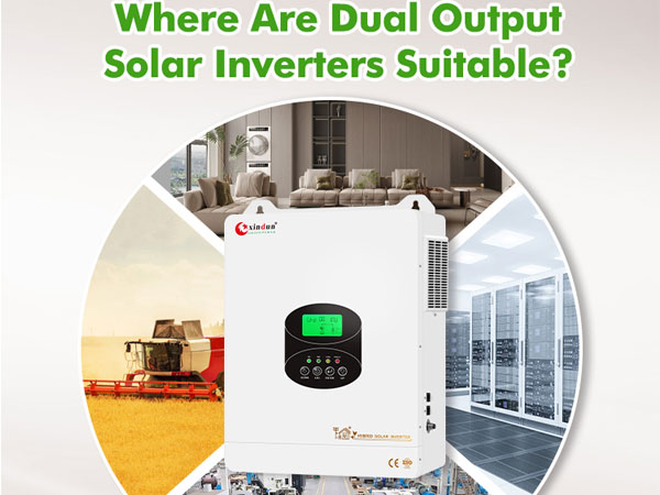
In solar power system, the inverter, as the core equipment for power conversion and distribution, directly affects energy utilization efficiency, equipment lifespan, and user electricity safety. Taking the Xindun hybrid inverter as an example, this inverter features 14 core protection functions across all scenarios, building a comprehensive safety barrier from solar input and battery energy storage to mains power interaction and load output, allowing users to enjoy green energy without worrying about equipment failures and safety risks.
So, what protection functions does the Xindun parallel hybrid inverter offer?
The output of solar array is susceptible to environmental factors such as sunlight and temperature. Voltage and current fluctuations can damage the inverter's core components.
The parallel hybrid inverter features triple protection at the solar input end, ensuring stable and reliable solar energy conversion process.
Solar Current Limiting Protection: When the solar array's charging current or power exceeds the inverter's rated value, the inverter will automatically charge at the rated current and power value to avoid overload impacts, ensuring conversion efficiency while preventing component overheating damage.
Solar Overvoltage Protection: If the solar voltage exceeds the maximum value allowed by the hardware, the inverter will report a fault and stop solar voltage boosting to output a sinusoidal AC wave, mitigating the risk of overvoltage breakdown at the source.
Nighttime Reverse Charging Protection: At night, when there is no sunlight, the battery voltage may be higher than the solar module voltage. In this case, the protection function automatically activates, preventing the battery from discharging backwards into the solar module, avoiding power loss and battery life degradation.
As the key to the system's energy storage, the battery's charging and discharging state directly affects the overall range and safety. The inverter offers multiple layers of protection for the battery, balancing safety and durability:
Battery Overvoltage Protection: When the battery voltage reaches the overvoltage cutoff point, the charging circuit between the solar and mains power is automatically cut off to prevent overcharging from causing battery bulging, leakage, or other damage, thus extending battery life.
Battery Undervoltage Protection: When the battery voltage drops to the low voltage cutoff point, discharging the battery will automatically stop to avoid damage to the battery's internal structure from deep discharge, ensuring battery cycle life.
Battery Overcurrent Protection: If the battery discharge current exceeds the hardware's allowable range, the device instantly shuts off the output and stops discharging, effectively avoiding the risks of current fluctuations caused by short circuits, poor wiring, etc.
In scenarios where the inverter is connected to mains power, fluctuations in grid voltage and frequency may affect equipment operation. The inverter ensures safe operation through precise monitoring and rapid response:
Mains Input Overvoltage Protection: When the voltage of each phase of the mains power exceeds 280Vac, mains charging is immediately stopped and the inverter output is switched to prevent grid fluctuations from impacting the equipment and load.
Mains Input Undervoltage Protection: When the voltage of each phase of the mains power is below 170Vac, mains charging is immediately stopped and the inverter output is switched to prevent grid fluctuations from impacting the equipment and load.
AC Reverse Current Protection: Prevents AC power generated by the battery inverter from flowing back into the bypass AC input, avoiding mutual interference between the grid and the equipment.
Bypass Wiring Error Protection: If the phases of the two bypass inputs are inconsistent with the phases of the inverter's individual phases, the equipment will be prohibited from switching to the bypass, effectively preventing safety hazards such as load power loss and short circuits, and ensuring the safety of the equipment and load in the event of wiring errors.
From the inverter's core circuit to the terminal load, protection functions are implemented throughout, mitigating multiple risks and addressing common hazards such as short circuits, overloads, and overtemperature:
AC Output Short Circuit Protection: When a short circuit fault occurs at the load output terminal, the output AC voltage will be immediately shut off. Output will resume after 1 minute. If the output load terminal remains short circuited after 3 attempts, the short circuit fault must be cleared before manually powering on again to restore normal output.
Overload Protection: After overload protection is triggered, the inverter will resume output after 3 minutes. Five consecutive overloads will shut down the output until the inverter restarts. (102% < Load < 110%) ± 10%: Error, output shuts down after 5 minutes. (110% < Load < 125%) ± 10%: Error reported and output shuts down after 10 seconds. Load > 125% ± 10%: Error reported, output shuts down after 5 seconds.
Heatsink Over-Temperature Protection: When the internal temperature of the inverter becomes too high, the inverter will stop charging and discharging. Once the temperature drops to a safe range, the inverter will automatically resume charging, preventing core components from aging or burning out due to overheating.
Bypass Overcurrent Protection: Built in AC input overcurrent protection circuit breaker quickly disconnects the faulty circuit when the bypass current is abnormal, providing dual safety protection for the equipment and the power grid.
Bypass Wiring Error Protection: When the phases of the two bypass inputs are different from the phases of the inverter's phase, the machine will prevent bypassing, preventing load power loss or short circuits when bypassing is activated.
|
|
HP PLUS+ Parallel Hybrid Inverter 10KW/12KW This inverter supports parallel operation, either single phase or three phase, with maximum of six units connected in parallel to meet varying power expansion needs. Furthermore, users can customize time of use charging and discharging settings according to their actual electricity consumption habits, effectively utilizing solar power generation. |
|
|
HU Series Parallel Hybrid Inverter 10KW/12KW It supports setting split phase input and split phase output, or US standard single phase input and single phase output functions, suitable for the dual voltage standard requirements of the US. It also supports parallel operation of 6 units in single phase or three phase configurations, suitable for flexible and expandable power projects. |
The protection functions of the Xindun parallel hybrid inverter effectively ensure the stable operation of the output and core circuitry, ensuring the inverter's safe and reliable operation and providing a solid guarantee for user power safety and long term equipment use.
The above are the common faults and protection functions of parallel hybrid inverter. If you have any further questions, please feel free to contact Xindun Power.